 Meteorologists would like to have more data on which to base their reports and predictions. But the weather stations that provide information on wind speed and direction, temperature, and rainfall are typically complex and expensive. A technique for transmitting both power and bidirectional data over a single twisted-wire cable is putting these concerns to rest. |
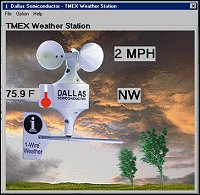 Photo 1. User-friendly software for the 1-Wire weather station runs on Win95 and displays an animated graphic representation of the actual station. The wind cups spin and the vane rotates as the wind blows and changes direction. |
Dan Awtrey, Dallas Semiconductor
To accurately describe current weather conditions and predict coming events, meteorologists need reliable data. Much of this information is collected from weather stations, and forecasters would like to have more of them. The problem is that conventional meteorological instrument systems are inefficient and expensive.
Each sensor in a weather station requires its own wiring and power supply. The sensor output must be signal conditioned before transmission. And adding sensors to an existing station means more wires and electronics.
A new weather station (see Photo 1, above), developed jointly by Dallas Semiconductor and Texas Weather Instruments, Inc., solves many of these problems by transmitting both power and bidirectional data over a single twisted-wire cable. This 1-Wire MicroLAN [1] uses a capacitor and diode half-wave rectifier to provide parasitic power from the data line for the station's various sensors and to transfer data (see Figure 1). Each sensor has a unique serial number that identifies it to the bus. The station is controlled by a PC or microprocessor executing Touch Memory Executive (TMEX) software. Data transfers are half-duplex and bit sequential over a single twisted pair using short and long time slots to encode the binary 1s and 0s.
 |
The basic weather station measures wind speed and direction, ambient temperature, and rainfall totals (see Figure 2). The package can be augmented with humidity, barometric pressure, and other weather sensors simply by connecting the sensor to the cable at the desired position and adding the appropriate software. Another option is to connect several weather stations to the same 1-Wire communication link for cost-effective measurement of laminar air flow patterns and other climatic parameters.
 |
Wind
Direction
Magnetically activated reed switches were selected
as the wind sensors for several reasons. They do not require power to
operate. Because they are neither motion nor rate dependent, they can
measure static conditions. They do not require signal conditioning. And
they have a very high impedance in the open state and negligible impedance
(150 m) when closed.
Interestingly, reed switches are normally rated as failed or end-of-life when the on resistance of the switch reaches 1 or 2 when operated at rated power level. A reed switch can operate over 100 million or more cycles at 50 V/100 mA levels or higher before failure. 1-Wire devices, which run at 5 V/4 mA, present almost no load, however, and can work with on resistance values of up to 100 . The functional lifetime of a reed switch in a 1-Wire environment such as the weather station is therefore much greater. Ongoing tests on the weather station show no degradation after more than 3 billion cycles.
The wind direction sensor consists of eight reed switches mounted radially on a PCB at 22.5º intervals (see Figure 3). Each switch is connected between the data line and a DS2401 silicon serial number that provides the switch's ID number. A rectangular activating magnet, polarized with a single pole facing the reed switch, is mounted in a rotor attached to the weather vane axle. The rotor is designed so that one layout can be used for both the wind speed and direction sensors. When the sensor is to be used for wind direction only, a single magnet is mounted in either of two holes near the rotor's center. As the wind rotates the vane and attached rotor, the magnet closes the switch as it passes over the reed.
 |
When a reed is closed, its companion DS2401 is connected to the bus (if the DS2407 addressable switch is on), and the bus master can read its serial number. This number identifies both the switch and the compass point it represents. For reasons of isolation, the bus master can read wind direction information only when the addressable switch is closed. Communication would otherwise be disrupted each time a reed switch closed and its associated serial number signaled its presence on the line.
Communication with the wind direction sensor begins when the bus master turns on the DS2407 output, connecting one side of all the DS2401s to the 1-Wire bus ground line. With its rotor and magnet, the weather vane activates (closes) at least one of the reed switches, connecting the other side of that DS2401 to the data line so the bus master can read its serial number. Because the master previously learned which compass point each DS2401 identifies, it knows which direction the vane is pointing when a particular DS2401 is on the bus.
The eight reed switches directly indicate eight compass points. Because of the magnet's length, however, when the magnet is approximately half way between two adjacent reed switches, both are closed. The bus master understands that this means the weather vane is midway between two compass points, so 8 additional points are inferred, for a total of 16.
Wind SpeedThe weather station handles wind speed measurements in a similar manner. The sensor consists of two magnets mounted on a second rotor attached to the wind cup's axle. The magnets operate a reed switch connected to the DS2423 counter chip that provides the sensor's serial number. One magnet is mounted in each of the two outermost holes of the rotor, providing two counts per revolution and thus improving response at low wind speeds. The two-magnet arrangement also provides rotational balance to the rotor, an important consideration given that the rotor can reach 2400 rpm in 160 km/h (100 mph) winds.
The counter chip keeps track of the total number of wind cup revolutions and transmits the data to the bus master on demand. The chip contains two 232-bit counters and can be powered for 10 yr with a small lithium battery. Power for the counter chip comes from diode CR1 and capacitor C1 (referring again to Figure 1), which form the half-wave rectifier that steals power from the data line. The counter can be reset to zero only when this parasitic power is lost.
The bus master calculates wind speed by taking the difference between two values stored in the counter, one generated before and the other generated after a clocked interval. The calculation also takes into account other factors such as the relationship of revolutions per minute to kilometers per hour.
TemperatureAmbient temperature is measured with the DS1820 1-Wire digital thermometer. This self-contained sensor measures temperature as the difference between two oscillators, one of which is temperature dependent. The sensor functions over a 55ºC to 125ºC range and provides uncorrected accuracy of ±0.5ºC over 0ºC to 70ºC. (For higher resolution, see the calculations in the data sheet.)
For measurement accuracy, this sensor would normally be mounted in a separate, ventilated housing. In accordance with the initial design's emphasis on simplicity, however, it was mounted on the weather station PCB. Because exposure to the sun can raise the inside of the housing to 20ºC over ambient, this arrangement can lead to large errors in reading. The problem can be solved by mounting an additional digital thermometer in a separate enclosure and adding it to the bus by plugging it into the daisy-chain connector on the PCB. A measurement of solar radiation may then be calculated from the difference between the two temperature readings. Indoor temperature can be measured with another DS1820 mounted in the desired location and connected to the same twisted pair going to the weather station. In fact, multiple DS1820s can be added on the 1-Wire cable to measure temperature anywhere along its length, up to 300 m.
RainfallRainfall is commonly measured with the fill-and-tip method. Rain enters the collector, drips through a small hole in its funnel-shaped bottom, and falls into one of two identical receptacles of known volume mounted on either end of a beam. One vessel is up, the other down. When the upper receptacle is full, that end of the beam pivots down. The water spills out and drains away. This action raises the lower receptacle into the up position and the cycle continues. Each time the beam moves, a magnet mounted to it momentarily closes a reed switch, with each closure typically representing 0.01 in. of rain. Because the system incorporates a DS2423 1-Wire counter chip with the reed switch, rainfall measurement capability can be added to the weather station by simply connecting its I/O pin to the twisted-pair bus.
Summary
1-Wire
technology offers several advantages over conventional weather
instrumentation. A single wire plus ground supplies power and
bidirectional communication. Because each sensor is identified by a unique
serial number, it is a simple matter to add sensors as needed at any point
on the twisted pair. In addition to the basic weather station package of
wind speed and direction, temperature, and rainfall sensors, devices are
available for the measurement of barometric pressure, humidity, lightning,
and soil moisture. Multiple weather stations sharing a single cable could
be mounted at various heights above the ground for real-time measurement
of laminar air flow or temperature variation with height. #A system
consisting of at least six 1-Wire weather stations is currently under
consideration for use on a television station transmitting antenna.
References
1. Dan
Awtrey. Feb. 1997. "Transmitting Data and Power Over a One-Wire Bus,"
Sensors:48-51.
Acknowledgments
The author wishes to thank David
Patterson of Texas Weather Station, Inc., and John Compton of Point Six,
Inc., for their cooperation and participation.
Dan Awtrey is a Staff Engineer, Dallas Semiconductor, 4401 S. Beltwood Pkwy., Dallas, TX 75244-3292; 972-371-6297, fax 972-371-3715, dan.awtrey@dalsemi.com
For information about the weather station, contact David Patterson, CEO, Texas Weather Instruments, Inc., 5942 Abrams Road #113, Dallas, TX 75231; 214-368-7116, fax 214-340-6264, www.texas-weather.com
For information about 1-Wire sensors, contact John Compton, CEO, Point Six, Inc., 138 E. Reynolds St., Lexington, KY 40517; 606-271-1744, fax 606-271-4695.