
Version 2.0 and 3.0 differ only in the available printed circuit (PC) boards and the choice of components. Both versions have the same precision. Version 3.0 can be built on a Version 2.0 PC board. Version 3.0 is a higher quality double sided board with plated through holes. Version 3.0 uses a terminal strip connector were as Version 2.0 uses a modular connector and DC socket.
As with 1-Wire Barometer Version 1.1a, this design uses a Motorola MPX4115 Silicon Pressure Sensor, a Dallas Semiconductor DS2438 Smart Battery Monitor (to perform 1-Wire analog to digital conversion), and an operational amplifier. It has two voltage regulators, two diodes, a LED, and several resistors and capacitors.
For background information please see the Version 1.1a web page.
| 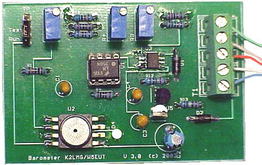 |
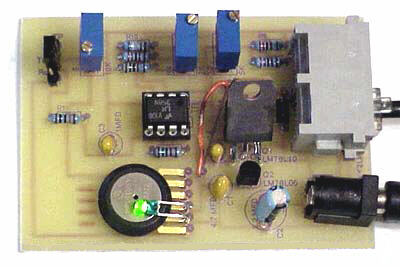
| Version 2.0 | Version 3.0 |
| Note the large 10 volt regulator between the opamp and the RJ11 connector. | Note the screw type connector and the missing DC socket. |
The circuit requires an additional power source other than that of the 1-Wire
network. The MPX4115 requires about 7 ma of current. This is more than a 1-Wire
network can provide without an elaborate circuit to store parasitic power from
the 1-Wire network for short burst of current for pressure measurements.
Two
voltage regulators are used to provide both 5.0 and 10.0 voltages from a source
of DC power ranging from 12 to 20 volts.
For barometric pressures the MPX4115 output voltage ranges from about 4.25 to 3.79 volts at sea level, and about 2.77 to 2.45 volts at 10,000 feet. Most of this range is above the active voltage range of a 5 volt opamp circuit. In effect the sensor voltage is referenced to the power supply, not ground as desired. Fortunately the DS2438 Smart Battery Monitor accepts inputs as high as 10 volts. Thus by powering an opamp from 10 volts the output of the MPX4115 is well in the opamp and DS2438 range.
The MPX4115 output is fed through a RC filter to opamp stage, U1B, which has a fixed gain of approximately 4. This stage has an adjustable voltage input which is added to the barometric sensor output within the opamp, thereby allowing the adjustment of the output voltage offset to the A/D converter.
This in turn is fed to opamp stage, U1A with an adjustable gain. It is capable of a gain range of 1/1 to about 4.14/1.
The two 10-turn potentiometers (pots) control the gain and offset. R3 controls the gain of U1A and R4 controls the offset of the output voltage to the 1-Wire DS2438 A/D converter.
Note that the MPX4115 feeds R1 through a jumper. This allows easy change of the input voltage from a source than the MPX4115 for calibration.
| Select the Version | |
| Version 2.0. Parts List and Calibration Details. | Version 3.0. Parts List and Calibration Details. |
Two simulators are provided:
| Select the download package for your barometer construction. | |
| Version 2.0. Large schematic with full details,
parts list, version 2.0 simulators, and calibration details. Need to help construction, for option modifications and calibration. The schematic will print on 8 x 10 paper. baro20package.zip. |
Version 3.0. Large schematic with full details,
parts list, version 3.0 simulator, and calibration details. Needed to help construction, for option modifications, and calibration. The schematic will print on 8 x 10 paper. baro30package.zip |
| Each of the above packages contain their own simulators. This pckage is all four simulators in one Zip download. simulators.zip. | |
| For making your own Version 2.0 printed circuit boards. baro20pc.zip. | |
Suggestions on Final Calibration
Once you have constructed your
barometer and done the initial calibration, it is recommended that you do a
final calibration after the barometer has been operated for several days.
Getting your barometer accuracy calibrated will take adjustment over several cycles of barometric pressure change. The initial calibration will not be accurate unless your MPX4115 has the same output vs pressure slope as the typical sensor.
Our recommendation is that you do not attempt to adjust the potentiometers of your barometer until you create a spreadsheet of local airport pressure vs your readings, and do this for a significant number of readings over a range of pressures.
Following is a 14 day data spreadsheet with a pressure range of 1.27 inHg --
29.31 to 30.58. The barometer was calibrated for a range of 28.8 to 30.8, giving
a resolution of 0.01 inHg. (This data was obtained from barometer V1.1a.)
Results
Once you have those results you can use a linear trendline (regression) to
find the slope of local vs airport readings. If the trendline slope is not 1.0,
use that slope to correct your gain resistor R3.
The slope will be a
multiplicitive change to the current R3 resistance. For example: if current R3
resistance is 3K and the slope is 1.05, change R3 to 3K/1.05 = 2.85K.
Before you spend too much time getting an accurate calibration you should decide what range of pressure changes you want to track and what range of output voltages of U1A you consider satisfactory.
Happy Construction!
The Version 1.1a web page gives complete details of its design. Those details largely apply to this design also.
The available Design Simulator computes much of this information. So only the very basic details are presented here.
To find the equivalent sea level barometric pressure at any altitude use the following formula:
pressure (inHg) = exp((log(1 - 6.87324e-6 * altitudeFt) * 5.256)) *
seaLevelPressure, or
pressure (kPa) = exp((log(1 - 22.5498e-6 *
altitudeMeters) * 5.256)) * seaLevelPressure;
To find this MPX4115 voltage output we can use the formula on the MPX4115 data sheet:
MPXVoltage = 5.0 * (0.009 * kPa - 0.095) or
MPXVoltage = 5.0 *
(0.009 * inHg * 3.3863 - 0.095)
Thus the maximum voltage is: 5.0 * (0.009 * 31 * 3.3863 - 0.095) = 4.25,
and
the minimum voltage at 28 in Hg is: 2.45.
A range of 4.25 to 2.45 is required to allow locations as high as 10,000 feet.
To get the very best resolution you need to establish the linear range of the opamp and DS2438. To do this:
Following is a sample graph for a barometer input voltage range of: 4.17 to 3.72 volts, and a A/D value of 3.25 to 1.27. Taken for barometer V1.1a.
The results show a very linear graph with a small standard error.
It would
appear that the upper range could be extended to 3.30, or 3.40 volts.
Resolution:
hiBaro = 31.0, loBaro = 28.0
hiOut = 8.25, loOut = 1.25
inHg/volts = (hiBaro - loBaro)/(hiOut - lowOut) = 0.428
A/D resolution =
2^10 / 10 volts = 100
barometer resolution = 0.428 / 100 = 0.00428 inHg.
This circuit is offered for noncommercial purposes only. Any other use must have prior written authorization from David W. Bray, or from Jim Jennings
 to
this page.
to
this page.
 Main Page