![]()

The conventional tipping bucket method of rainfall measurement can be adapted for incorporation into an automated weather station.
Dan Awtrey,
Dallas Semiconductor
The classic
professional rain gauge operates by filling and dumping two buckets, one
mounted on either end of a beam that pivots around a central axle in a
manner somewhat reminiscent of a playground seesaw (see Figure 1).
Rainwater gathered in the lid portion of the gauge trickles down into the
upper bucket through a small-diameter hole in the lid's funnel-shaped
bottom. When the bucket has received the proper amount of water, it
empties itself by pivoting around the axle and pouring the water into the
base. This action raises the other bucket into position and the cycle
repeats. Holes in the base allow the water to drain away.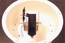
Each time a bucket empties its contents, it moves a magnet past a magnetic reed switch and causes it to close. With each closure typically representing 0.01 in. of rainfall, to measure 1 in. of rain each bucket must empty 50 times for a total of 100 switch closures. This tipping bucket technique can be adapted to work with the 1-Wire weather station.
Dallas Semiconductor, in conjunction with Texas Weather Instruments, Inc., previously developed a basic weather station that measures wind speed, wind direction, and temperature using Dallas's 1-Wire technology [1]. Adding a rain gauge to the station requires only that it be connected to the 1-Wire bus by plugging it into the unused RJ11 connector on the weather station board. Because 1-Wire technology transmits both power and bidirectional data over a single twisted-pair cable [2,3], no extra wiring or power is required.
The station is controlled by a PC or microcontroller executing Touch Memory Executive (TMEX) software. Data transfers are half-duplex and bit sequential over a single twisted-pair cable using short and long time slots to encode the binary ones and zeros. Each 1-Wire device in the weather station has a unique serial number that identifies it to the bus master, allowing multiple sensors to share the same bus.
Measuring Rainfall the 1-Wire Way
Adapting the standard tipping bucket rain gauge mechanism to operate on the 1-Wire net is a simple matter of wiring its reed switch between the power and count inputs of a DS2423 counter (see Figure 2). While the counter will function with just the parasite power supplied by CR1b and C1, the lithium battery backup allows the rain gauge to function in a stand-alone mode without an online PC. The low energy requirements of the chip allow for up to 10 years of service life. If this capability is not needed, CR2a and the lithium backup can be omitted.
 |
| Figure 1. In a tipping bucket apparatus, rainfall is gathered in the funnel-bottomed lid and dripped into one of two buckets. When the required water volume is reached, the bucket falls and empties. The action moves the other bucket into position to repeat the process. |
When connected to the 1-Wire net, the circuit works in the following manner: The idle position for the bus is at 5 V, supplied through the equivalent of a 1.5 k(omega) pull-up resistor at the bus master. This forward biases Schottky diode CR1b and charges capacitor C1 to ~5 V, supplying all operating power for the DS2423 counter U1.
Whenever the tipping bucket empties, its magnet swings past reed switch SW1, causing it to close momentarily and pulling the counter inputs to a logic high. When the reed switch opens again, the pull-down resistor R1 returns the inputs to a logic low. The counter chip keeps track of the total and transmits the data to the bus master on command.
Since the DS2423 does not have a reset pin, setting the rain gauge to zero must be handled in software by the tare method. The counter does, however, reset to zero when all power is removed for about a minute, so if the gauge is expected to work even when the PC is off, CR2 and the battery backup must be added. Schottky diode CR1a protects the circuitry from voltage excursions that go below ground; the DS2407 contains 1 K of OTP EPROM for storing data specific to the rain gauge.
The rain gauge is calibrated by allowing 16 oz. of water to drip slowly through the lid over a 1 hr period. This should result in each bucket's dumping 50 times for a reading of 1.00 in. of rain. That means the two calibration screws shown in Figure 1 must be adjusted so that 0.16 oz. of water causes the bucket to dump. Turning the screw to raise the bucket higher above the base decreases the amount of water required to cause a pour and thus increases the count. Conversely, turning the screw to lower the bucket closer to the base decreases the count. Because of the response time to tip and empty a bucket, trying to calibrate the unit with too fast a drip rate can lead to unacceptable errors.
 |
| Figure 2. A magnet on the tipping bucket mechanism momentarily closes the magnetic reed switch each time a bucket tips and empties. This increments the DS2423 digital counter one count. Power for the counter is normally supplied by CR1b and C1. Lithium battery backup can be added using CR2a to allow rainfall to be recorded even when the bus master is off-line. |
The pull-down arrangement of R1 on the DS2423 was chosen to increase its noise rejection capability, but it also permits an interesting option. An n-channel FET can be connected across the resistor, with the gate at point A and the source to ground. Normally, R1 pulls the gate down and keeps the transistor off, but when the tipping bucket empties, its magnet closes the reed switch and briefly turns the transistor on. This provides a useful digital switch with bare drain output for other purposes such as adding an LCD readout.
Summary
The rain gauge is a useful and desirable addition to the 1-Wire weather station and demonstrates the ease with which additional sensors may be added to a 1-Wire net. Because each sensor is identified by a unique serial number, other sensors or 1-Wire devices may be added at any time and placed where needed on the bus without rewiring or supplying power.
References
1. Dan Awtrey. June 1998. "The 1-Wire Weather Station," Sensors:34-40.
2. ------. Feb. 1997. "Transmitting Data and Power over a One-Wire Bus," Sensors:48-51.
3. ------. MicroLAN Design Guide, www.dalsemi.com/techbriefs/tb1.html
Acknowledgments
The author wishes to acknowledge David Patterson of Texas Weather Instruments, Inc., for his cooperation and participation, and Dang Nguyen and Nhung Pham of Dallas Semiconductor for handling all the little thankless details.
Dan Awtrey is a Staff Engineer, Dallas Semiconductor, 4401 S. Beltwood Pkwy., Dallas, TX 75244-3292; 972-371-6297, fax 972-371-3715, dan.awtrey@dalsemi.com
For weather station information, contact David Patterson, CEO, Texas Weather Instruments, Inc., 5942 Abrams Rd. #113, Dallas, TX 75231; 214-368-7116, fax 214-340-6264, www.texas-weather.com
For information about available 1-Wire sensors, contact John
Compton, CEO, Point Six, Inc., 383 Codell Dr., Lexington, KY 40509;
606-266-3606, fax 606-266-0702, www
.pointsix.com