Transmitting Data and Power over a One-Wire Bus
A clever circuit technique that "steals" power from the data line allows the transfer of bidirectional data while supplying power to remote devices over a single conductor.Dan Awtrey, Dallas Semiconductor
Sensors and modules are being connected to computers, often PCs, in increasing numbers to answer the demand for more communication links and instrumentation. Information typically flows between computer and sensor or module over multiconductor cable consisting of separate communication and power conductors such as the 2-wire I2C bus. Note that by convention the ground or reference wire is not normally counted. Alternatively, an external source of power can be supplied along the cable as needed. A clever circuit technique that "steals" power from the data line allows a versatile new communication system to transfer bidirectional data while supplying power to remote devices over a single conductor. This is the 1-wire MicroLAN.
The 1-wire system uses a capacitor and diode half-wave rectifier to provide parasitic power for a line of products, including identification devices, read/write memories, addressable switches, and digital temperature sensors. This technique can eliminate the cost of extra wires or remote power supplies. Significantly, each device contains a unique individual identification code and a self-timing controller. This article introduces the MicroLAN and describes its features.
The MicroLAN
The MicroLAN is a network standard that allows
PCs and microcontrollers to communicate digitally over twisted pair cable
with 1-wire components. It is defined as an open-drain (wired-AND)
master/slave multidrop architecture with a resistor pullup to a nominal 5
V supply at the master. The network consists of three main elements: a bus
master and its controlling software, the wiring and associated connectors,
and the 1-wire device. Any standard microcontroller such as an 8051 with
at least a 1.8 MHz clock, or a PC using a 115.2 kbps capable UART
(universal asynchronous receiver/ transmitter), can serve as master. The
UART supplies 1-wire timing by sending a byte for each 1-wire bit, using
short and long time slots to encode the binary 1s and 0s. At this 14.4
kbps data rate (115.2 / 8 = 14.4 kbps), the PC can address a node on the
bus and begin receiving data in <7 ms.
Optional Touch Memory EXecutive (TMEX) software is included with the DS0621-SDK professional software developer's kit. The MicroLAN protocol uses conventional CMOS/TTL logic levels, with 0.8 V or less indicating a logic level zero and 2.2 V or greater a logic level one. It operates from a minimum of 2.8 V to a maximum of 6 V. Data transfers are half- duplex and bit sequential over a single pair of wires, data and return, from which the slaves steal power by means of an internal diode and capacitor. The DS9097 COM port adapter can interface RS-232 to the MicroLAN, and cheap, readily available Category 5 unshielded low-capacitance twisted-pair phone wire is recommended for the bus.
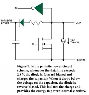
As previously noted, data on the MicroLAN are transferred with respect to time slots. To write a logic one to a 1-wire device, for example, the master holds the bus low for 15 ms or less. To write a logic zero, it holds the bus low for at least 60 ms to provide a timing margin for worst-case conditions. No system clock is required because each 1-wire part is self-clocked by its own internal oscillator. Power for operation is derived from the bus data line by including a half-wave rectifier on chip.
As shown in Figure 1, when the data line is pulled high by the
bus pullup resistor, the diode in the half-wave rectifier turns on and
charges the 800 pF internal capacitor. The stored charge provides energy
to power the internal oscillator and control circuitry during the times it
actively pulls the bus low to signal a logic one or zero to the master.
Charge lost during these time slots is replenished when the data line
again crosses the 2.8 V threshold that turns on the half-wave rectifier
diode. This concept of stealing power from the data line by a half-wave
rectifier is referred to as parasite power.
In operation, the master resets the network by holding the bus low for 480 ms and looking for a responding presence pulse from any slave connected to the line. The master then accesses the slave by calling its address, issues any additional family-specific commands required by that device, and then performs any necessary data transfers between it and the slave. It controls the information transfer by generating time slots and examining the response from the slave. The address of each device is stored in a lasered ROM section with its own guaranteed unique, 48-bit serial number that acts as its node address. With 248 serial numbers available, there will never be a problem with conflicting duplicate node addresses on the LAN. This capacity easily surpasses that of other existing network standards.
The 48-bit serial number is part of a larger 64-bit code programmed into each 1-wire device at the factory. An 8-bit family code is stored in the first byte and identifies the device type as NVRAM, EEPROM, temperature sensor, timekeeper, etc. The next 6 bytes store the unique individual serial number; the last byte contains a cyclic redundancy check with a value based on the data contained in the first seven bytes. This allows the master to determine if an address was read error free.
A Simple LAN
The simplest possible MicroLAN would use a PC
with a DS9097 COM port adapter and a single DS2401 silicon serial number
on the bus. This part is intended for applications where positive
identification is required, but can also be used to check whether a switch
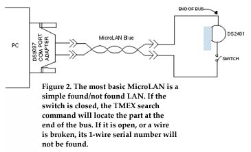
is open or closed. When the DS2401 is connected to the net through the
switch (see Figure 2), the master can find and read its serial number
using TMEX search command software.

When the switch is open, the part is not connected to the bus so its serial number will not be found by the master. By this simple found/ not-found technique it is possible to ascertain the presence or absence of virtually anything.
For example, a DS2401 hard wired at the far end of a bus can determine line integrity. If the search command finds the part at the cable end by calling its serial number, the bus is intact. Conversely, if the device serial number is not found, the wiring is open. In like manner, it is possible to monitor the position of doors and windows in a secured area to determine whether they are open or closed.
And if a part containing memory, such as the DS2502 with 1 Kb of EPROM, is used in place of the DS2401, additional data about the entity to which it is attached may be read by the master. In effect, these become electronic labels scribed in silicon and can be used for inventory control, identification badges, personnel data, etc., to monitor the location and movement of tagged items. Referred to as automatic identification, these electronic labels are offered in stainless steel cans and solder-mount packages as iButtons or decoder rings (see sidebar), or Touch Memories. A single MicroLAN bus can be up to 300 m long and contain literally hundreds of electronic labels. The actual number of 1-wire devices on the LAN will usually be limited by the time needed to read all the devices, or the physics of the two wires that form the bus. For example, it takes about 12 s to do a search command on a mix of 500 1-wire devices using a COM port adapter on a PC. Since timing is controlled by the UART, microprocessor clock speed has no impact on the search time.
Memory in the LAN
iButton devices can be formatted with a
file directory just like that on a floppy disk. A directory allows files
to be randomly accessed and changed without disturbing other records.
Information is read or written when an identification badge or decoder
ring is connected to a computer master by touching it to a port somewhere
along the MicroLAN bus. A typical port would consist of an outer ring
conductor and a spring-loaded center conductor mounted in an appropriate
housing. The ring touches the case of the iButton or decoder ring and
connects it to the return line of the bus. The spring-loaded center
contact touches the lid and connects it to the bus data line. The
inclusion of memory in the 1-wire chips allows standard information such
as employee name and ID number to be stored within the device and, with up
to 64 K available, other data besides.
For example, it would take only about one-fourth of the available memory to store the equivalent of a business card and digitized black-and-white ID photograph. This still leaves generous space for other important data such as medical records, credit information, or security level. With such information literally at hand (in the case of the decoder ring), reliable identification and access are readily available and machine readable.
Summary
The 1-wire MicroLAN is an inexpensive,
easy-to-install network standard with multidrop capability. It uses
commonly available PCs or microcontrollers such as the 8051 as a master,
and can supply both data and power over low-cost twisted-pair cable. With
its guaranteed unique serial numbers and multidrop capability it can
identify and read 1-wire devices permanently attached to structures along
the bus, as well as roving devices such as ID tags or decoder rings.
One-wire parts with memory capability allow data to be collected off bus
and transferred to the computer master by touching a port somewhere along
the MicroLAN bus. Functionally, a port consists of little more than
elegant exposed sections of the twisted pair constituting the bus that
touches both the lid and case of the iButton or decoder ring. When
connected, the master can address and begin transferring data with the
device in about 7 ms.
The 1-wire MicroLAN is useful in applications such as warehousing, where stocking information can be collected as items are added to or removed from the shelves. Simply touching an iButton or decoder ring to a MicroLAN port serves to record who performed the transaction and when. Other applications include access control and, if encoded according to the American Banking Association Standard, even serving as substitutes for the standard plastic credit card.
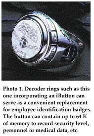
The Decoder Ring The decoder ring (see
Photo 1) contains a user-selectable iButton 1-wire chip and a 3 V
lithium battery. Each chip is individually numbered with one of
248 available serial numbers stored in a ROM section that
serves as its guaranteed unique address and ensures against
conflicting duplicate addresses. Various chips may be specified by
the customer, ranging from the DS1990A that provides simple
identification (and requires no backup battery) to the DS1986 with
64 K of EPROM arranged as 256 by 256 bits. Each part can be
formatted like a floppy disk with a file directory that allows
specific files to be randomly accessed without disturbing other
records. The decoder ring (see
Photo 1) contains a user-selectable iButton 1-wire chip and a 3 V
lithium battery. Each chip is individually numbered with one of
248 available serial numbers stored in a ROM section that
serves as its guaranteed unique address and ensures against
conflicting duplicate addresses. Various chips may be specified by
the customer, ranging from the DS1990A that provides simple
identification (and requires no backup battery) to the DS1986 with
64 K of EPROM arranged as 256 by 256 bits. Each part can be
formatted like a floppy disk with a file directory that allows
specific files to be randomly accessed without disturbing other
records.
The chip is first packaged in a coin-style battery case 16 mm in dia. with an embossed lid. The two-piece stainless steel package acts as both a protective housing and the electrical contacts. The case serves as return contact (ground) and the lid as data contact. The package size permits inclusion of a lithium cell to provide 10 years of standby power to maintain data in volatile RAM memory when not connected to the LAN. The case is set in a semicustom or custom piece of jewelry from Jostens Inc. (Minneapolis, Minnesota). Information is read or written when the decoder ring is connected to a computer master by touching it to a port somewhere along a MicroLAN bus. A typical port would consist of an outer ring conductor and a spring-loaded center conductor mounted in an appropriate housing. The port's outer conductor touches the case of the iButton and connects it to the return line of the bus, while the spring-loaded center contact connects the lid to the bus data line. Communication is controlled by the PC with its UART that sends a byte for a bit. At 115.2 kbps, a PC can address a decoder ring on the bus and begin receiving data in <7 ms. |
The author wishes to acknowledge colleagues Syd Coppersmith, Dennis Jarrett, Bernhard Linke, and Jeff Owens, whose valued input made this article possible.
Dan Awtrey is a Staff Engineer, Dallas Semiconductor, 4401 S. Beltwood Pkwy., Dallas, TX 75244-3292; 972-371-6297, fax 972-371-3715. For more information about MicroLAN products, contact Dennis Jarrett, Dallas Semiconductor, 972-371-4416, fax 972-371-3715, dennis.jarrett@dalsemi.com